To understand what is keyshaft machining and how does it work, begin with the part itself. A keyshaft usually transfers torque through a machined keyway. This groove holds a key, which connects the shaft to a gear, pulley, or coupling. Its dimensions must match closely. Even a small error can create vibration, backlash, or early wear.
Professor Yusuf Altintas, a leading authority in machining science, explains, “Successful machining depends on controlling the process, not simply removing material.” This principle applies directly to keyshaft production. A machinist may turn the shaft on a CNC lathe, then mill or broach the keyway. Cutting speed, tool geometry, material hardness, and coolant all affect the result. The workpiece must remain firmly supported. Otherwise, deflection can leave the groove uneven.
Inspection matters just as much. Technicians check shaft diameter, keyway width, depth, position, and surface finish. They may use micrometers, plug gauges, a coordinate measuring machine, or a profilometer. The final fit should feel secure, not forced. It should also allow correct assembly.
The process is not flawless.
Heat can distort the shaft. Tool wear can change the groove profile. A drawing may look complete while missing an important tolerance. That is where experienced review helps. This guide will explain the equipment, machining sequence, common defects, and practical inspection methods behind keyshaft production.
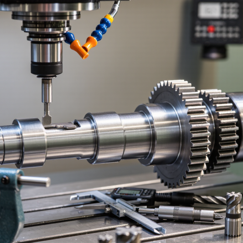
Keyshaft machining is the controlled process of shaping a shaft with one or more precise keyways. These grooves hold keys that connect the shaft to gears, pulleys, or couplings. The connection transfers torque without unwanted slipping. It also keeps rotating parts aligned during operation.
A machinist may begin with turning, which creates the shaft’s diameter and shoulder locations. A milling cutter or broaching tool then forms the keyway. Its width, depth, and position must match the mating component. Even a small error can cause vibration, rapid wear, or difficult assembly. Cutting fluid helps control heat and protects the tool edge. The finished part may show fine tool marks. Those marks are not automatically defects.
Inspection is essential. Technicians commonly use micrometers, height gauges, plug gauges, and coordinate measuring equipment. They check diameter, concentricity, keyway dimensions, and surface condition. Material choice also matters because steel, stainless alloys, and hardened materials behave differently during cutting. In practical production, clear drawings and recorded measurements improve repeatability. Still, machining is not perfectly predictable. Tool wear, clamping pressure, and temperature can change results. A careful shop reviews unexpected readings instead of hiding them. That habit supports safer assemblies and more dependable machine performance.
How Keyshafts Are Designed for Power Transmission
A keyshaft transfers torque between a rotating shaft and a hub, gear, or coupling. Its design starts with power, speed, and duty cycle. Engineers often use T = 9550P/n, where T is torque in newton-metres, P is kilowatts, and n is revolutions per minute. The keyway then carries torque through two contact faces. Sharp corners are risky. They increase stress concentration and may trigger fatigue cracks. Material strength, shaft diameter, key length, and fit must work together. The IEA’s Energy Efficiency Policy Opportunities report estimates that motor-driven systems consume 43–46% of global electricity. Better shaft alignment can therefore reduce losses across many industrial machines.
Machining accuracy affects real performance. A controlled keyway width prevents looseness, while correct depth protects the remaining shaft section. Surface finish also matters near shoulders and fillets. In practical inspection, engineers check runout, hardness, dimensional tolerance, and burr removal. A small burr can disturb a hub fit. Small errors grow. ISO 21940 balancing guidance also reminds designers to control rotational imbalance, especially at higher speeds. Yet a perfect drawing can still fail when loading changes suddenly. This is where fatigue calculations, trial testing, and maintenance records become valuable. The design may need revision.
Tips: Confirm the actual load spectrum, not only rated power. Measure the mating hub before cutting the keyway. Use generous fillets, suitable heat treatment, and calibrated gauges. Record wear patterns after operation; they often reveal misalignment earlier than a calculation.
The chart shows the theoretical torsional torque capacity of solid steel shafts with different diameters. Values are calculated using an allowable torsional shear stress of 40 MPa and represent ideal shaft capacity before accounting for keyway stress concentration, fatigue, deflection, or key failure.
Larger shaft diameters transmit substantially more torque because torsional capacity increases approximately with the cube of shaft diameter. Precision machining of the keyway is essential for reliable torque transfer between the shaft and hub.
Keyshaft machining depends heavily on material selection. The shaft must resist torque, wear, bending, and repeated loading. Medium-carbon steel is common for general mechanical applications. Alloy steel suits higher loads and improved fatigue resistance. Stainless steel helps in humid or corrosive environments. Aluminum reduces weight, but it may wear faster under heavy contact. Bronze can work well where sliding friction matters.
Machinists usually begin with a turning lathe. It creates the shaft diameter and prepares accurate shoulders. Milling machines or slotting machines cut the keyway. Broaching is useful when many identical keyways require consistent dimensions. CNC equipment can control complex profiles and repeated operations efficiently. Carbide cutting tools handle harder materials and maintain their edge longer. High-speed steel tools remain useful for smaller jobs and slower cutting conditions. The correct coolant also reduces heat and protects the cutting edge.
Measurement is just as important as cutting. Micrometers check shaft diameter, while calipers provide quick dimensional checks. Dial indicators help reveal runout during setup. A depth gauge confirms keyway depth. In practice, no setup is perfect. Tool deflection, vibration, and heat can change the final size. I have found that checking dimensions between operations prevents expensive rework. Material choice can also look correct on paper, yet fail under real operating loads. Load history and surface condition deserve closer attention.
Keyshaft machining begins with a clear engineering drawing and a suitable steel blank. The machinist checks diameter, length, keyway size, and required tolerances before cutting. Material condition matters because internal stress can cause later distortion. I have seen a shaft appear accurate after turning, then move slightly during heat treatment. That risk should be considered early.
The blank is secured carefully in a lathe, often between centers for better alignment. Turning creates the main diameters, shoulders, and end features. Cutting speeds depend on the material, tool geometry, and machine rigidity. After turning, milling or broaching produces the keyway. The cutter must enter smoothly and remove chips effectively. A rough keyway may weaken the shaft or create poor contact with the mating component. Small details matter.
Heat treatment can improve hardness and wear resistance, but it may change dimensions. Many workshops leave a small grinding allowance before this stage. Final grinding then improves surface finish and dimensional accuracy. Inspectors use micrometers, gauges, and runout indicators to check critical areas. They also examine the keyway for burrs, sharp damage, and proper depth. Not every defect is obvious by sight. A second measurement is often worthwhile, especially when the first result seems perfect. Calibration records and inspection notes support consistent production, although no process removes every possibility of human error.
Keyshaft inspection starts with geometry, not appearance. Technicians measure diameter, keyway width, shoulder location, and total indicated runout. A dial indicator reveals whether the shaft rotates evenly. Small marks matter. Surface cracks may begin near keyway corners, where stress concentrates during torque changes. Magnetic particle testing can expose surface and slightly subsurface cracks in suitable ferromagnetic shafts. Hardness testing then checks whether heat treatment created the intended strength.
Finishing removes burrs without weakening functional edges. Technicians lightly chamfer sharp corners, polish bearing seats, and verify surface roughness with a profilometer. The keyway must remain within drawing tolerances after finishing. ISO 1101 supports controlled geometric tolerancing, while ISO 21940 addresses balancing for rotating components. A shaft can pass dimensional checks and still vibrate. That is an important weakness in routine inspection. Final checks should include concentricity, balance, cleanliness, and a documented visual review. Records should identify the instrument, calibration date, reading, and inspector.
Tips: Use the same measurement points every time. Check for fretting dust around the key and keyway. It often signals micro-movement before visible damage appears. Follow the manufacturer’s maintenance interval, but adjust it after load, temperature, and vibration trends change. The U.S. Department of Energy’s Operations & Maintenance Best Practices Guide reports that predictive maintenance may reduce downtime by 30–40% and maintenance costs by 8–12%. These figures are useful benchmarks, not guarantees. I would review them against actual plant history. Clean oil, correct lubrication, torque checks, and early replacement of damaged keys can protect the shaft and connected equipment.
Keyshaft machining shapes a shaft and cuts one or more precise keyways. These grooves hold keys for gears, pulleys, or couplings. The connection transfers torque and limits unwanted slipping. Small errors matter.
The keyway must match the mating component’s width, depth, and position. Poor accuracy can cause vibration, rapid wear, or difficult assembly. It can also weaken contact between the shaft and connected part. Perfect results are not always guaranteed.
Medium-carbon steel suits many general mechanical applications. Alloy steel handles higher loads and repeated stress. Stainless steel performs well in humid or corrosive surroundings. Aluminum reduces weight but may wear faster. Bronze can help where sliding friction is important.
A lathe creates the shaft diameter, shoulders, and end features. Milling or slotting machines cut the keyway. Broaching suits repeated keyway production with consistent dimensions. CNC equipment helps control complex and repeated operations. Carbide tools suit harder materials. High-speed steel remains useful for smaller jobs.
The process begins with a drawing, material blank, and required tolerances. The blank is clamped carefully, often between centers. Turning creates the main diameters and shoulders. Milling or broaching then forms the keyway. Heat treatment may improve hardness and wear resistance. Final grinding can improve accuracy and surface finish.
Micrometers check shaft diameter. Calipers provide quick dimensional checks. Depth gauges verify keyway depth. Dial indicators reveal runout during setup. Coordinate measuring equipment can check position and concentricity. Technicians also inspect burrs, sharp damage, and surface condition. A second measurement is often worthwhile.
Yes, heat treatment can alter dimensions because internal stress may be released. Workshops often leave a small grinding allowance before treatment. Final grinding corrects some dimensional changes. A shaft may look accurate after turning, then shift slightly later. That possibility deserves early attention.
Tool wear, vibration, clamping pressure, and temperature can change the final size. Tool deflection may produce an undersized or misplaced keyway. Excessive heat can damage the cutting edge or affect accuracy. Fine tool marks are not automatically defects. Unexpected readings should be reviewed, not hidden. Check twice.
Keyshaft machining is a precision manufacturing process used to produce shafts with keyways or other shaped features that securely transfer torque between rotating components. The article explains what is keyshaft machining and how does it work by covering how engineers design keyshafts for reliable power transmission, including correct dimensions, tolerances, load capacity, and alignment. It also discusses common materials, such as steel and other durable alloys, along with cutting tools and machining equipment selected for strength, accuracy, and wear resistance.
The process generally includes material preparation, turning, milling or slotting the keyway, drilling, threading when required, and removing sharp edges. After machining, keyshafts are inspected for dimensional accuracy, surface quality, straightness, and proper fit. Finishing treatments may improve durability and corrosion resistance, while regular cleaning, lubrication, alignment checks, and wear inspections help maintain dependable performance throughout the shaft’s service life.

SHE Auto