Top 10 Ways to Improve Precision in Shaft Machining?

Time:2026-10-16 Author:Henry
0%

Precision in shaft machining is no longer judged by appearance alone. A shaft may look mirror-bright yet fail during assembly because of taper, runout, or thermal drift. For manufacturers asking how to improve precision in shaft machining, the answer begins with controlled evidence, not assumptions. Every critical diameter, concentricity value, and surface-finish result should connect to a verified measurement method.

Industry data reinforces this need. Deloitte’s 2023 Smart Manufacturing and Operations Survey found that 86% of manufacturing leaders viewed smart manufacturing as a major competitiveness driver within three years. However, digital tools cannot correct poor fixturing or an unstable cutting process. The U.S. National Institute of Standards and Technology, through its manufacturing metrology guidance, emphasizes traceability, uncertainty evaluation, and calibrated equipment. ISO 230-1 also provides a recognized framework for assessing machine-tool accuracy and repeatability. These sources point toward the same practical lesson: precision depends on the entire process chain.

Small details matter. A worn collet can shift a shaft by several micrometres. A hot spindle can change the result before inspection begins. Tool overhang, coolant temperature, chuck pressure, and probing technique deserve equal attention. Not every shop has the budget for full automation. That is acceptable. Disciplined setup records and repeatable checks often deliver meaningful gains first. Still, this article does not promise perfect results. Real machining involves vibration, material variation, and operator judgment. The following ten methods examine where precision is commonly lost and how measurable improvements can be built into daily shaft production.
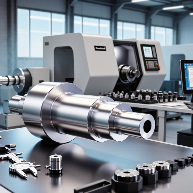
Top 10 Ways to Improve Precision in Shaft Machining?

Define Precision Requirements and Select Suitable Shaft Materials

Precision in shaft machining starts with a number, not a vague promise. State the required diameter tolerance, straightness, roundness, surface roughness, and runout. These values should match the shaft’s actual duty. For a bearing seat, a 0.02 mm diameter tolerance may be critical. A less demanding section may accept more variation. Specify runout at the working diameter, not only at the chuck. That small distinction often exposes alignment errors. Ask how measurements will be taken. A drawing can be precise, yet a weak inspection method creates false confidence. Use calibrated micrometers, consistent temperature, and documented measurement points.

Material selection must follow the load, speed, environment, and finishing process. Medium-carbon steel may machine cleanly, but heat treatment can introduce distortion. Stainless alloys resist corrosion, yet they may generate heat and harden during cutting. Aluminum is light and easy to cut. It can still deform under clamping pressure. Check hardness before machining, then check it again after treatment. Leaving extra stock for final grinding is often safer than chasing size in one operation. Still, this is not universal. Thin shafts may bend during grinding. Support them properly. I have seen a shaft pass diameter inspection and fail assembly because its shoulder corner was slightly wrong. That mistake was not dramatic, but it was expensive. Precision depends on the complete requirement, the selected material, and honest verification.

Choose the Right Machine Tools, Cutting Tools, and Workholding Methods

Precision in shaft machining starts with machine selection, not polishing the final pass. Choose a rigid turning center with verified spindle runout, thermal stability, and repeatable axis movement. ISO 230-2:2014 separates positioning accuracy from repeatability, so both values deserve inspection before production. A machine can repeat a wrong position perfectly.

Cutting tools must match the shaft material, diameter, and required surface finish. Use a sharp, stable insert with suitable edge geometry and controlled nose radius. Excessive tool overhang increases vibration. Keep the holder short. The 2023 U.S. Cutting Tool Consumption Report, published by USCTI and AMT, recorded approximately 2.6 billion dollars in tool consumption. That figure reflects how strongly tooling affects industrial productivity. However, higher tool spending does not automatically create better parts. Tool wear still needs measurement.

Workholding often decides whether a shaft stays straight. Use a properly aligned chuck, soft jaws bored at the actual clamping diameter, or a steady rest for long workpieces. Support both ends when deflection becomes visible. Check runout with a calibrated indicator before cutting. NIST guidance on dimensional measurement emphasizes traceable calibration and uncertainty control. That matters here. I have seen setups fail because the operator measured only the finished diameter. The first setup is rarely perfect. Recheck after warm-up, especially when tolerances are tight.

Top 10 Ways to Improve Precision in Shaft Machining? — Choose the Right Machine Tools, Cutting Tools, and Workholding Methods
No. Precision Improvement Area Recommended Practice Typical Engineering Target or Effect Main Benefit Verification Method
1 Select a rigid, thermally stable machine tool Use a machine with adequate spindle power, a rigid bed, low-backlash axis drives, and effective thermal management. Allow the machine to reach a stable operating temperature before final sizing. Maintain consistent dimensional results during extended cycles; thermal drift should be characterized for the specific machine and process. Reduces vibration, positional error, and size variation caused by heat buildup. Machine warm-up routine, laser or ball-bar checks, and periodic dimensional inspection.
2 Use a suitable turning or cylindrical-grinding process Use finish turning for efficient general precision and cylindrical grinding when very low surface roughness, close size control, or hardened-material finishing is required. Finish turning commonly produces approximately Ra 0.8–3.2 µm; grinding can achieve approximately Ra 0.2–0.8 µm when properly controlled. Matches the process capability to the required tolerance and surface finish. Surface roughness measurement and dimensional inspection with calibrated gauges.
3 Choose the correct cutting-tool geometry Select insert nose radius, rake angle, clearance angle, and edge preparation according to material, diameter, depth of cut, and finishing requirements. Use a smaller nose radius for slender shafts when cutting-force control is critical. Common finishing nose radii are about 0.2–0.8 mm; the final value must suit rigidity, feed rate, and chip control. Controls cutting forces, deflection, chatter, burr formation, and surface texture. Check tool geometry, cutting-edge condition, chip form, and finished profile.
4 Apply appropriate cutting parameters Set cutting speed, feed, and depth of cut using the tool and workpiece material recommendations, then reduce feed and radial engagement for the final finishing pass when necessary. A finishing allowance of roughly 0.1–0.3 mm on diameter is often used, but the correct allowance depends on material, tool geometry, and machine rigidity. Limits cutting-force variation and improves repeatability of diameter and form. Monitor spindle load, vibration, tool wear, and the measured size of successive parts.
5 Use stable workholding and proper support Use a precision chuck, collet, soft jaws bored at the actual clamping diameter, or a between-centers setup. Add a steady rest or follower rest for long, slender shafts. For slender shafts, a length-to-diameter ratio above approximately 10:1 commonly requires additional support, depending on material and cutting conditions. Reduces workpiece runout, bending, vibration, and movement during cutting. Verify chuck or collet runout with a dial indicator at the workholding and machining locations.
6 Control workpiece runout and alignment Clean all contact surfaces, indicate the workpiece where required, align centers accurately, and inspect chuck jaws, centers, and locating shoulders for damage or contamination. A practical setup goal is to keep runout within the drawing requirement; high-precision setups may target a few micrometres at the working diameter. Improves concentricity between turned features and reduces taper caused by misalignment. Dial indicator checks, test cuts, and measurement of concentricity between functional diameters.
7 Use coolant and chip control correctly Direct coolant consistently into the cutting zone, select a fluid compatible with the work material, and prevent chips from recutting or becoming trapped between the workpiece and the fixture. Stable coolant delivery helps reduce thermal variation and improves tool life; exact flow and pressure depend on the machine and tool system. Reduces heat-related size changes, built-up edge, surface damage, and unpredictable tool wear. Check coolant concentration, temperature, nozzle position, chip shape, and surface finish.
8 Manage tool wear and tool-life limits Establish a tool-life limit based on measured wear and part quality rather than waiting for tool failure. Use tool offset adjustments only within a controlled correction range. Replace or recondition the tool when wear begins to affect size, form, burrs, or surface finish; the limit is application-specific. Prevents gradual dimensional drift and inconsistent surface quality between batches. Tool-wear checks, in-process probing, statistical trend charts, and first-off inspection.
9 Measure during and after machining Use calibrated micrometers, air gauges, bore gauges, probes, or a coordinate measuring machine according to the feature size and tolerance. Measure at a controlled temperature. Measurement resolution should be appropriate to the tolerance; a common practice is to use equipment with resolution no greater than one-tenth of the tolerance. Detects drift early and separates machine, tool, fixture, and material-related errors. Calibration records, gauge repeatability checks, temperature control, and documented inspection results.
10 Use a controlled finishing sequence Rough machine first, leave a consistent finishing allowance, allow the workpiece to stabilize when heat is significant, then complete finishing in one repeatable setup whenever possible. Maintain a consistent roughing allowance and avoid removing excessive material during the final pass, which can increase deflection and thermal variation. Improves cylindricity, straightness, concentricity, and repeatability across production batches. Inspect size, taper, roundness, straightness, and concentricity against the engineering drawing.

Optimize Cutting Parameters for Stable and Accurate Machining

Stable shaft machining begins with controlled cutting parameters, not aggressive speed.

Set spindle speed from material hardness, tool diameter, and allowable surface speed. Then adjust feed per revolution to protect dimensional accuracy. A 50 mm shaft may show chatter when feed rises before the tool engages properly. The surface can look acceptable, yet the diameter may drift by several micrometres near the shoulder.

The U.S. Energy Information Administration’s 2023 Annual Energy Review places industry near 32% of total U.S. energy consumption. This makes efficient cutting relevant, but lower power alone does not guarantee precision. Monitor spindle load, vibration, and cutting temperature during trial passes. ISO 230-2 also emphasizes machine positioning accuracy, so verify axis movement before blaming the cutting tool.

Keep tool overhang short. Check runout with a dial indicator. Use a consistent coolant flow around the cutting zone.

A practical starting point is a moderate cutting speed, steady feed, and shallow finishing depth. Change one variable at a time. Otherwise, the results become difficult to interpret.

I have seen operators reduce speed too far and create rubbing, heat, and poor finish. That approach feels safe. It is not always safe. Record measured diameter, surface roughness, and tool wear after every test batch. Small deviations often reveal unstable parameters before rejected shafts appear.

Control Heat, Vibration, and Tool Wear During the Process

Precision in shaft machining depends on controlling heat, vibration, and tool wear together. A sharp tool can still produce taper when heat shifts the workpiece centerline. I monitor coolant flow, spindle load, and part temperature near the cutting zone. Cutting tests should record temperatures, not rely on touch. ISO 230-3:2020 provides methods for evaluating thermal displacement in machine tools. Its guidance supports warm-up cycles and repeatable measurement routines.

Vibration often appears as faint rings on the shaft surface. I reduce it by shortening tool overhang, checking workholding pressure, and matching cutting speed to the shaft’s stiffness. A 2023 U.S. cutting-tool consumption report valued domestic consumption at about 2.76 billion dollars. That figure reflects how costly tool selection and replacement can become across industry. Yet tool cost is not the only issue. A worn edge increases cutting force, heat, and dimensional drift. Replace tools by measured flank wear, not appearance alone. This is where my own practice remains imperfect.

I sometimes extend tool life too far. That mistake can ruin an entire batch. Use a fixed inspection interval, then adjust it from recorded wear data. Check the first article after any insert change. Measure diameter at several points along the shaft. Small thermal errors become visible there. Keep vibration logs beside inspection results. Patterns are easier to find than isolated failures.

Inspect Shaft Dimensions and Refine the Manufacturing Workflow

Precision in shaft machining starts with trustworthy dimensional inspection. A drawing tolerance is not a suggestion. It controls every setup, cut, and acceptance decision. Measure the diameter at several axial positions and rotate the shaft during inspection. This exposes taper, ovality, and local tool marks. Use calibrated micrometers for finished journals and a height gauge for shoulder locations. Record temperature too. Steel expands enough to distort close-tolerance readings. Keep parts and instruments near 20°C before judgment. A clean surface matters. Chips can create false measurements.

Refine the workflow by linking inspection results to each machining stage. Check raw stock after sawing, then inspect runout after turning. Verify journal size before grinding, not only after it. This prevents expensive finishing work on a poorly aligned part. Use a repeatable datum and stable workholding. Soft jaws may need boring in the same setup. Mark inspection points on the route sheet, with the operator, tool condition, and measurement time. Review trends rather than isolated numbers. Five readings drifting toward the upper limit signal wear. Adjust the tool before rejection becomes routine.

I have seen teams trust final inspection too much. That habit hides process variation. A second measurement by another trained inspector can reveal technique differences. Still, double-checking cannot repair weak control. Set realistic sampling intervals and investigate every unexplained shift. Keep revision-controlled records, including gauge calibration status. Do not chase perfect numbers blindly. Functional fit, surface finish, and concentricity must support the shaft’s actual service. Sometimes our process looks stable because we measured too little. That deserves correction.

FAQS

What should you check before selecting a machine tool for shaft machining?

Choose a rigid turning center with low spindle runout and stable thermal behavior. Check positioning accuracy and repeatability separately. A machine can repeat a wrong position perfectly.

How should cutting tools be matched to the shaft?

Match the insert to the material, diameter, and required surface finish. Use a sharp edge with a controlled nose radius. Keep the holder short.

Why is workholding important for long shafts?

Poor support can bend the shaft during cutting. Use aligned chucking, accurately bored soft jaws, or a steady rest. Support both ends when deflection becomes visible.

How can operators reduce chatter and vibration?

Reduce tool overhang and use steady cutting conditions. Begin with moderate speed, consistent feed, and a shallow finishing cut. Do not change several variables together.

What cutting parameters should be monitored during trial passes?

Watch spindle load, vibration, cutting temperature, and coolant flow. A 50-millimeter shaft may chatter when feed rises too quickly. Lower speed is not always safer.

How should shaft dimensions be inspected?

Measure each journal at several axial positions. Rotate the shaft during inspection to reveal taper and ovality. Use calibrated micrometers for finished diameters.

Why should temperature be recorded during close-tolerance inspection?

Steel expands with temperature and can distort the reading. Keep parts and instruments near 20°C before final judgment. Clean away chips first.

How can inspection results improve the machining workflow?

Inspect raw stock after sawing and check runout after turning. Verify journal size before grinding begins. Record tool condition, measurement time, and operator details.

What does a pattern of measurements near the tolerance limit indicate?

Five readings drifting upward may indicate tool wear. Adjust the tool before rejection becomes routine. Do not trust one final measurement.

Is repeated inspection enough to ensure a reliable process?

No. A second inspector may reveal technique differences, but weak control remains. Review trends, calibration status, and unexplained shifts. Our process may seem stable because we measured too little.

Conclusion

Improving shaft machining precision begins with clearly defining dimensional tolerances, surface-finish requirements, and performance expectations. Selecting a suitable shaft material is equally important, since hardness, strength, thermal expansion, and machinability directly affect process stability. To understand how to improve precision in shaft machining, manufacturers should match machine tools, cutting tools, and workholding methods to the shaft’s geometry and production needs. Rigid setups, properly aligned equipment, and sharp, application-appropriate tools help reduce deflection and improve consistency.

Precision also depends on optimizing cutting speed, feed rate, and depth of cut for stable material removal. Heat, vibration, and tool wear should be monitored and controlled because they can cause dimensional drift, surface defects, and premature tool failure. Finally, shafts should be inspected at key stages using reliable measurement methods, with results used to refine tool offsets, process sequences, and inspection plans. A continuous workflow of measurement, analysis, and adjustment can improve accuracy, repeatability, and overall manufacturing efficiency.

Henry

Henry

Henry is a dedicated marketing professional with a profound expertise in the company's offerings. With years of experience in the industry, he possesses an impressive understanding of the market dynamics and consumer behaviors that drive success. Henry is committed to sharing his insights through......