Why Do Machined Shafts Fail and How to Fix Them?

Time:2026-10-21 Author:Sophia
0%

Machined shafts often look simple, yet their failure patterns can be surprisingly complex. A shaft may leave the lathe with a bright surface and precise dimensions. Later, it can bend, crack, wear unevenly, or fail under a load that seemed acceptable. This raises an important question: what are common issues in machining shafts, and how can engineers correct them before failure reaches the field?

Common causes include excessive runout, incorrect diameter, poor concentricity, sharp shoulder transitions, residual stress, and unsuitable surface finishes. Tool wear can leave subtle marks around a journal. Misalignment may create one-sided wear near a bearing seat. Heat treatment can also produce distortion that normal turning operations cannot fully remove. In practice, inspection must go beyond calipers. Engineers often use dial indicators, micrometers, roundness checks, hardness testing, and documented process measurements. Small details matter.

W. Edwards Deming, a respected quality expert, stated, “Quality comes not from inspection, but from the improvement of the production process.” That principle applies directly to shaft manufacturing. Inspection catches defects, but stable tooling, controlled speeds, proper support, and repeatable setup prevent them. Still, no process is perfect. A drawing may omit a critical operating load. An operator may trust a familiar setup too much. That deserves reflection. This article examines why machined shafts fail, how evidence reveals the root cause, and which practical repairs can restore performance without repeating the same mistake. It connects workshop experience with engineering analysis, material behavior, and disciplined quality control.
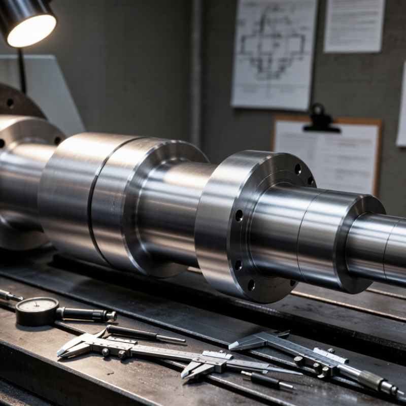
Why Do Machined Shafts Fail and How to Fix Them?

Define Shaft Failure Modes: Fatigue Causes About 90% of Breakdowns

Machined shafts rarely fail without a warning hidden in their surface. Fatigue causes about 90% of rotating-shaft breakdowns, although the exact rate varies by industry and operating conditions. Repeated bending, torsion, and vibration create microscopic cracks. These cracks often begin at keyways, shoulders, threads, or rough machining marks. A small notch can become a serious stress concentrator.

The fracture surface tells an important story. Beach marks may show slow crack growth, while a final bright area indicates sudden overload. Inspectors should also check alignment, bearing condition, balance, and actual operating loads. A shaft may look properly sized on paper but still fail after thousands of load cycles. That is where design assumptions deserve another review.

Repair starts with the cause, not only the broken part. Improve fillet radii, remove sharp tool marks, and control surface finish. Select suitable material and heat treatment for the real load spectrum. Check hardness and residual stress when fatigue damage appears early. Correct misalignment and vibration before installing a replacement shaft. Shot peening may improve surface durability in suitable applications, but it is not a universal fix. Corrosion, fretting, and poor lubrication can quietly reduce fatigue life. One overlooked detail can undo careful machining. The 90% figure is a useful warning, not a complete diagnosis. A reliable failure analysis combines measurements, fracture evidence, maintenance records, and honest questioning of the original design.

Locate Stress Risers: Keyways and Threads Can Cut Fatigue Life by 25%

A machined shaft rarely fails without a clue. The clue is often a stress riser. Keyways, threads, sharp shoulders, and abrupt diameter changes concentrate load. Under repeated bending or torsion, these small geometric details become crack-starting points. In some shaft designs, a keyway or thread can reduce fatigue life by about 25%. The number is not universal. Material, surface finish, load direction, and heat treatment change the result.

During a failure review, inspect the keyway corners first. A square corner acts like a notch. A generous radius spreads stress more smoothly. Check thread runouts too, especially where the threaded section meets a larger diameter. That transition often carries more stress than the thread crest. Use magnetic-particle or dye-penetrant inspection when surface cracks are suspected. Measure the radius, depth, and surface roughness instead of relying on sight. A shaft may look perfect. It may not be.

Repair starts with the load path, not the file or grinder. Remove damaged material only if the remaining diameter still meets the design calculation. Replace sharp keyway ends with properly radiused ends, and improve thread relief where possible. Keep machining marks away from high-stress fillets. Verify hardness and alignment after machining. I have seen well-polished repairs fail because the original stress concentration was never redesigned. That mistake is easy to repeat. Calculate stress concentration factors, compare them with fatigue data, and test the finished shaft under realistic loading. If the design margin is unclear, stop guessing and involve a qualified mechanical engineer.

Why Do Machined Shafts Fail? Fatigue-Life Impact of Stress Risers

Notches such as keyways and threads create local stress concentrations. Compared with a smooth reference shaft, these features can reduce fatigue life substantially, especially when surface finish and geometry increase the notch effect.

The values show representative normalized fatigue life under the same cyclic bending load. A smooth shaft is indexed at 100%; a standard keyway is shown at 75%, while a sharp-root thread is shown at 65%. Improve performance by increasing fillet radii, using rolled or fine-root threads, improving surface finish, and avoiding abrupt section changes.

Inspect Shafts Using ASTM E18, ASTM E1444, and Dimensional Tolerances

Why Do Machined Shafts Fail and How to Fix Them?

Machined shafts usually fail through fatigue, overload, corrosion, or poor fit. Inspection must connect evidence with the original drawing. ASTM E18 measures Rockwell hardness and helps verify heat-treatment consistency. Test several locations, not only the polished end. A single reading can hide a soft core or a hardened edge.

ASTM E1444/E1444M magnetic particle testing reveals surface and near-surface cracks in ferromagnetic shafts. Clean the shaft first, magnetize it in two directions, and record crack length and position. A 2023 NASA reliability guide links fatigue failures with stress concentration, misalignment, and repeated loading. NIST measurement guidance also stresses uncertainty, traceability, and calibrated equipment. These details matter when a crack is only a few millimeters long. Hardness alone cannot explain everything.

Tips: Compare diameter, runout, shoulder radius, keyway width, and bearing-seat geometry with the drawing. Use ISO 286 fits when specifying limits, then verify actual values with calibrated micrometers and gauges. Check runout near the bearing seat and at the coupling end. Review the process route, too. Grinding burns and sharp tool marks may become failure origins. I once trusted a clean-looking surface and missed a shallow keyway crack; that mistake still deserves attention. Record temperature, gauge resolution, operator, and measurement location. Retest questionable results before approving rework.

Redesign for Fatigue: Steel Endurance Limits Often Approach 0.5×UTS

Why Do Machined Shafts Fail and How to Fix Them?

Redesign for Fatigue: Steel Endurance Limits Often Approach 0.5×UTS

Machined shafts usually fail after repeated loading, not one dramatic overload. A rotating shaft experiences tension and compression during every revolution. Small flaws can therefore become serious cracks. In many steels, the endurance limit under ideal reversed bending may approach 0.5 times the ultimate tensile strength (UTS). This is only a starting estimate. Surface roughness, shaft diameter, heat treatment, corrosion, and temperature can reduce it sharply.

The fillet is often the real problem. A sharp shoulder creates stress concentration near the bearing seat. A visible crack may begin below the surface, where inspection is difficult. I once reviewed a shaft design that passed a static strength check but failed near its keyway. The calculation missed notch sensitivity. That mistake was expensive. A larger fillet radius, smoother machining, and a properly proportioned relief groove can lower local stress. Keyways may also require generous radii and careful alignment.

Use fatigue analysis, not only yield-strength calculations. Apply correction factors for surface finish, size, reliability, and mean stress. Confirm the design with finite element analysis, then inspect prototypes using magnetic-particle or dye-penetrant methods where appropriate. Measure hardness and verify the actual material condition. Do not trust a polished surface alone. It may hide a poor subsurface finish or residual tensile stress. Sometimes the best redesign is less dramatic: reduce the bending span, improve support alignment, or eliminate an unnecessary groove.

Why Do Machined Shafts Fail and How to Fix Them? — Redesign for Fatigue
Failure Area Typical Design or Operating Condition Observed Failure Evidence Engineering Interpretation Recommended Redesign or Repair Useful Design Target
Sharp shoulder or step change Fillet radius below 0.5 mm at a diameter transition; bending stress concentrated at the shoulder. Crack origin at the fillet, often followed by a smooth beach-mark region. The theoretical stress concentration is amplified by the notch sensitivity of the shaft material. Increase the fillet radius, use a blended or relieved shoulder, and verify clearance for mating components. Use the largest practical radius; a radius of 1.5–3.0 mm is commonly more fatigue-resistant than a sharp corner.
Keyway or spline-root stress concentration Torque transmitted through a full-depth keyway with a sharp internal corner. Crack starts at the keyway end or at the root of the spline and grows across the shaft section. Material removed from the shaft reduces the effective section modulus while the groove raises local alternating stress. Add rounded keyway ends, increase root radius, reduce unnecessary keyway depth, or consider a properly designed spline or shrink-fit connection. Avoid sharp internal corners; specify a controlled root radius and inspect the groove after machining.
Alternating bending stress too high Rotating shaft experiences a bending moment of 450 N·m with a 35 mm minimum diameter. Fatigue fracture occurs after repeated operation without a single overload event. For a solid circular shaft, bending stress is approximately σ = 32M/(πd³); small diameter reductions greatly increase stress. Increase the minimum diameter, reduce overhung load, improve bearing support, or shorten the load distance. For 450 N·m and 35 mm diameter, nominal bending stress is approximately 337 MPa before concentration and surface factors.
Combined bending and torsion Simultaneous bending and torque create non-zero mean and alternating stresses. Failure surface is angled or shows multiple crack origins near a geometric discontinuity. Checking bending and torsion separately can underestimate the equivalent alternating stress. Use a combined fatigue criterion, such as modified Goodman or Soderberg, and include stress-concentration factors for both loads. Evaluate alternating and mean von Mises stress rather than relying only on static yield strength.
Insufficient fatigue strength assumption Material UTS is 800 MPa and the preliminary endurance estimate is based on polished laboratory specimens. Design passes a static strength check but fails during high-cycle service. For many steels, the unmodified rotating-beam endurance limit may approach 0.5 × UTS, but real shafts are reduced by surface, size, reliability, notch, and environment factors. Start with the laboratory estimate, then apply Marin-type modification factors and a suitable fatigue safety factor. Unmodified estimate: approximately 400 MPa; practical design value may be substantially lower after corrections.
Poor machined surface finish Turning marks remain perpendicular to the principal bending stress; surface roughness is approximately Ra 3.2 µm. Crack initiation follows machining marks or tearing near the fillet. Surface valleys act as small notches and reduce fatigue strength, especially in high-strength steel. Improve finishing at critical regions, orient machining marks favorably, remove torn material, and avoid abrupt tool exits. Specify a finer finish for critical fillets, commonly Ra ≤ 0.8–1.6 µm where practical.
Residual tensile stress Grinding burn, aggressive machining, or straightening leaves tensile stress at the surface. Early surface cracks, discoloration, local hardness change, or crack networks after grinding. Tensile residual stress adds to operating tensile stress and accelerates crack initiation and growth. Control grinding heat, use coolant correctly, remove damaged material, and verify hardness or residual stress when failure risk is high. Do not accept visible grinding burn or unverified thermal damage in a fatigue-critical zone.
Corrosion-assisted fatigue Steel shaft operates with moisture, salt, chemicals, or inadequate sealing. Rust pits are located at crack origins; fracture life is shorter than laboratory fatigue predictions. Corrosion pits act as sharp surface notches and continuously remove protective material. Improve sealing and drainage, select a suitable corrosion-resistant material or coating, and remove pits before reuse. Treat corrosion protection as part of the fatigue design, not only as a cosmetic requirement.
Misalignment or excessive bearing load Coupling, bearing, or housing alignment produces an unintended radial load and cyclic bending. Uneven wear, heat, fretting, or a crack on one preferred side of the shaft. Misalignment can convert nominal torsion-only service into combined bending and torsion. Check alignment, bearing fits, shaft runout, coupling condition, and actual load paths under operating temperature. Measure runout and alignment under assembled conditions; do not rely only on unloaded bench measurements.
Inadequate diameter transition Large diameter changes occur over a short axial distance with no relief groove or smooth blend. Crack begins at the smaller diameter immediately beside the transition. Load flow is disturbed and the local stress concentration factor increases. Use a gradual transition, generous fillet, undercut relief where appropriate, and sufficient axial length for the change in diameter. Confirm the local fatigue stress using a notch factor, not the nominal small-diameter stress alone.
Overload or accidental impact Torque exceeds the design value or a jam creates a transient shock load. Gross plastic deformation, torsional shear lips, or a fracture with limited fatigue progression. A single overload can initiate a crack or permanently damage a fatigue-critical surface. Add torque limiting, overload protection, stronger couplings, or a larger shaft section; inspect after abnormal events. Separate static overload protection from the high-cycle fatigue calculation.
Poor fit or fretting at a joint Hub, bearing, or shrink-fit interface experiences micro-slip under fluctuating load. Dark fretting debris, circumferential marks, and cracks near the fit edge. Micro-motion damages the surface and creates local stress concentrations. Review fit class, contact pressure, edge relief, surface hardness, and joint stiffness; prevent relative motion where possible. Inspect the fit edge carefully because fretting cracks may be small before final fracture.
Insufficient inspection coverage Fatigue-critical shaft is accepted using only visual inspection. Small surface-breaking cracks remain undetected until sudden failure. Fatigue cracks may grow substantially before they become visible to the unaided eye. Use magnetic-particle testing for suitable ferromagnetic steels, dye penetrant testing for surface defects, or ultrasonic testing for relevant internal flaws. Define inspection intervals using load history, crack-growth risk, and the consequence of shaft failure.
Design note: A steel endurance limit near 0.5 × UTS is a preliminary estimate for some polished, small laboratory specimens. A production shaft should use corrected fatigue strength that accounts for surface finish, size, notch effects, reliability, mean stress, residual stress, corrosion, temperature, and the actual load spectrum.

Control Fits and Balance with ISO 286 and ISO 21940 Requirements

Why Do Machined Shafts Fail and How to Fix Them?

Machined shafts often fail because fit and balance are treated as separate tasks. They are not. A tight fit can distort a shaft. An uneven keyway can create harmful centrifugal force. ISO 286-1 defines tolerance grades from IT01 to IT18, helping engineers select repeatable limits for diameter, hole, and shaft fits. For rotating assemblies, ISO 286 fit classes such as H7/g6 or H7/k6 should match load, temperature, lubrication, and service speed. A drawing alone is not enough.

ISO 21940-11 defines balance quality grades, including G2.5 and G6.3. The correct grade depends on rotor speed and application sensitivity. A practical calculation uses residual unbalance, rotor mass, and operating speed.

Even a small mass error becomes significant near a bearing seat. Industry maintenance reports repeatedly identify imbalance and misalignment among major vibration sources, while condition-monitoring studies link vibration growth with premature bearing damage.

These reports support measurement, but they cannot replace engineering judgment. Sometimes, our tolerance choice is simply too optimistic.

Tips:

Measure the shaft and housing at several points, not one. Record actual temperatures during operation. Check runout before balancing. Remove burrs around shoulders and keyways. Verify the final balance after assembly, because fit pressure can change geometry. Use calibrated gauges and keep traceable inspection records. ISO 21940 should guide the balance specification, not serve as a substitute for testing. Small errors matter.

FAQS

What causes most rotating-shaft failures?

Fatigue causes about 90% of rotating-shaft breakdowns. Repeated bending, torsion, and vibration create tiny cracks. The exact percentage varies. Operating conditions matter.

Where do fatigue cracks usually begin?

Cracks often start at keyways, shoulders, threads, or rough machining marks. These features concentrate stress. A small notch can grow dangerously.

How can a fracture surface reveal the failure process?

Beach marks may show slow crack growth. A bright final area can indicate sudden overload. The fracture surface is useful evidence, not a complete diagnosis.

Can a keyway or thread reduce shaft fatigue life?

Yes. In some designs, either feature may reduce fatigue life by about 25%. The effect depends on material, finish, loading, and heat treatment.

What should inspectors check besides the broken shaft?

Check alignment, bearing condition, balance, vibration, and actual operating loads. Measure keyway depth, corner radius, and surface roughness. Do not trust appearance alone.

How should a damaged shaft be repaired?

Start with the failure cause, not just the broken part. Remove damaged material only when the remaining diameter remains acceptable. Redesign sharp corners where possible.

Why are rounded keyway ends and larger fillets helpful?

Rounded ends spread stress more smoothly. Larger fillets reduce abrupt stress concentration. Sharp corners can behave like tiny wedges.

Can polishing or shot peening permanently prevent fatigue failure?

No. Surface improvements may increase durability in suitable applications. They cannot correct misalignment, overload, corrosion, or poor lubrication. A polished repair can still fail.

When should a mechanical engineer review the shaft design?

Seek qualified review when the design margin is unclear or cracks appear early. Compare stress concentration factors with fatigue data. Stop guessing. Test realistic loads when practical.

Conclusion

Machined shafts can fail for several reasons, but fatigue is responsible for roughly 90% of breakdowns in many applications. Repeated bending, torsion, overload, poor surface finish, and misalignment gradually create cracks that may lead to sudden fracture. Common stress risers include keyways, sharp shoulders, grooves, and threads, which can reduce fatigue life by about 25% when poorly designed or finished. Understanding what are common issues in machining shafts helps engineers identify risks early and improve reliability.

Effective prevention combines inspection, accurate manufacturing, and fatigue-focused design. Hardness checks can follow ASTM E18, while magnetic particle inspection according to ASTM E1444 can reveal surface and near-surface cracks in suitable materials. Critical dimensions, fits, runout, and surface conditions should also remain within specified tolerances. For redesign, engineers should consider that a steel endurance limit may approach 0.5 times its ultimate tensile strength, then add suitable fillets, improve surface quality, and reduce abrupt geometry changes. Proper fits based on ISO 286 and balanced operation aligned with ISO 21940 further help control vibration, wear, and premature failure.

Sophia

Sophia

Sophia is a dedicated marketing professional with an exceptional depth of knowledge about her company's products and services. With a keen understanding of market trends and customer needs, she crafts insightful blog posts that not only inform but also engage readers, enriching the company’s online......