How to Ensure Quality in Machined Components?

Time:2026-10-25 Author:Aria
0%

How to ensure quality in machined components begins with control at every stage, not final inspection alone. A turned shaft may look flawless under bright lights, yet fail because its bore is several microns too tight. Quality lives in those small details.

W. Edwards Deming, a leading authority on manufacturing quality, stated, “Quality comes from the improvement of the production system.” His principle remains highly relevant to modern machining. Reliable results depend on capable machines, trained operators, stable materials, and verified measurement methods. Engineers should review drawings, tolerances, surface-finish requirements, and material certificates before cutting begins. They should also confirm tool offsets, coolant conditions, fixture stability, and inspection frequency.

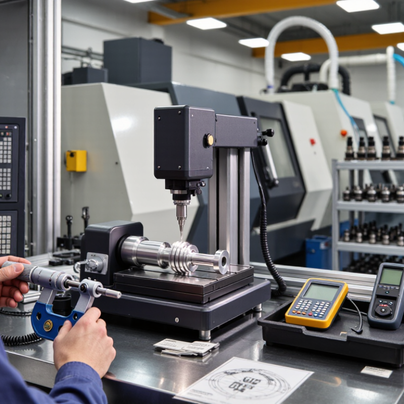
Measurement must be practical. A calibrated micrometer, height gauge, CMM, or surface roughness tester can reveal problems that visual checks miss. Production records should connect each component with its machine, operator, material batch, and inspection result. This traceability supports accountability and faster corrective action.

Still, no process is flawless. Even experienced teams can overlook tool wear or thermal expansion during long production runs. That uncomfortable possibility deserves attention. A strong quality system encourages questions, not silent confidence. Statistical process control, first-article inspection, and documented corrective actions provide useful safeguards. However, paperwork alone cannot guarantee precision. How to ensure quality in machined components requires evidence from real parts, consistent processes, and honest review. The goal is not perfection on paper. It is dependable performance in the customer’s assembly, where a few microns can determine success or failure.
How to Ensure Quality in Machined Components?

Define Quality Requirements for Machined Components

How to Ensure Quality in Machined Components?

Define Quality Requirements for Machined Components

Quality starts before cutting begins. A drawing should define material grade, critical dimensions, tolerances, surface finish, hardness, and edge conditions. Avoid vague terms such as “high precision.” State measurable limits instead. For example, specify a 20.00 ± 0.03 mm bore, Ra 1.6 μm, and a clear inspection method. In production, unclear requirements create disputes, rework, and delayed approvals. That weakness is often designed into the process.

The 2023–24 World Quality Report identifies data quality and traceability as persistent manufacturing challenges. A 2023 smart-manufacturing survey found that 86% of manufacturing leaders expect digital operations to improve competitiveness within five years. Digital tools help, but they cannot repair incomplete specifications. Define critical-to-quality features and link each feature to gauges, coordinate measuring machines, or validated testing. Record calibration status, operator, batch, and inspection results. Consider process capability targets, such as Cpk 1.33, only when the customer and process justify them. One number cannot fit every component.

Tips: Write acceptance criteria beside each key feature. Use a ballooned drawing during review. Challenge tolerances that lack functional purpose. Verify measurement uncertainty before rejecting parts. Sample inspection can reduce cost, but it may miss unstable processes. Pilot runs reveal this uncomfortable gap.

Select Suitable Materials, Machines, and Cutting Tools

Material, machine, and cutting-tool choices define machined component quality before production begins.

Select materials with stable hardness, predictable grain structure, and reliable certification records. Aluminum, stainless steel, and hardened alloys react differently to heat and vibration. Treat them as separate engineering problems.

Machine rigidity matters as much as spindle power. A rigid structure reduces chatter, while accurate thermal control protects dimensional stability during long cycles. Check spindle runout, axis backlash, coolant delivery, and probing accuracy before cutting.

The 2022 ISO Survey reported more than 1.26 million ISO 9001 certificates worldwide. That figure reinforces the value of documented inspections and traceability, not just final-part testing.

Cutting tools also need disciplined selection. Match carbide grade, edge geometry, coating, and nose radius to the workpiece. An oversized nose radius may improve finish but increase cutting forces. I have seen good programs fail because the tool was technically suitable, yet poorly suited to the machine.

Tips:

Record tool life by material, speed, feed, and surface finish. Use a short trial cut. Measure the first part at several points, including a difficult corner. Replace worn tools before burrs appear.

The U.S. Department of Energy identifies compressed-air leaks as a common source of industrial energy waste, so inspect coolant and air systems too. Do not trust one successful batch. Variation eventually exposes weak assumptions.

Control Machining Processes and Operating Conditions

How to Ensure Quality in Machined Components?

Consistent quality begins with controlled machining processes and stable operating conditions. In practice, I monitor spindle warm-up, coolant temperature, tool wear, cutting speed, and fixture pressure before production starts. A small temperature change can alter part dimensions, especially during long cycles. Measure it.

Statistical process control helps reveal drift before defects multiply. Record critical dimensions after setup, then sample parts at planned intervals. Use control charts, not intuition alone. The U.S. Department of Energy’s Improving Compressed Air System Performance sourcebook reports that air leaks can waste 20–30% of compressor output in poorly maintained systems. That loss can reduce clamping reliability and disturb pneumatic equipment. ISO 230-3 also emphasizes evaluating thermal behavior in machine tools, supporting warm-up routines and temperature tracking. However, these references cannot replace tests on your specific machine, material, and shop layout.

Tips: Keep coolant concentration within the supplier’s specified range, and check it with a refractometer. Replace worn tools before surface finish changes become visible. Verify probes and gauges against traceable standards. Review alarms daily. A perfect setup on paper can still fail after an unnoticed fixture shift. I have also seen operators over-trust one inspection point; that habit needs correction. Use layered checks, clear records, and documented reaction plans when measurements move toward control limits.

Inspect Dimensions, Surface Finish, and Material Integrity

How to Ensure Quality in Machined Components?

Dimensional inspection starts with the engineering drawing, not the finished part. Confirm critical diameters, hole positions, flatness, and tolerances before production begins. Use calibrated micrometers for tight features and a coordinate measuring machine for complex geometries. Record actual readings, not only pass or fail results. A small size shift can affect assembly, sealing, or load distribution. Check several locations on each feature. Heat from machining can change measurements.

Surface finish needs practical control. A profilometer provides Ra and Rz values, while visual checks reveal scratches, chatter marks, burrs, and tool lines. Inspect sealing faces under consistent lighting. Clean the component before measuring. Oil can hide small defects. I have seen acceptable numerical readings paired with visibly uneven surfaces. That mismatch deserves investigation. It may indicate measurement variation or an unsuitable inspection area.

Material integrity requires more than matching a certificate to a purchase order. Verify grade, heat-treatment records, hardness, and traceability. For critical parts, use positive material identification and suitable non-destructive testing. Look for cracks, inclusions, porosity, and distortion after machining. Keep inspection records linked to the part or batch. No inspection plan is perfect. Sampling can miss isolated defects, especially in cast or welded stock. Review failures honestly, then adjust inspection frequency, tooling condition, or machining parameters. The best evidence combines measured dimensions, documented surface data, and verified material history.

Document Results and Improve Production Quality

Quality in machined components depends on more than a final inspection. It depends on what the production team records during each operation. In my experience, useful records include material batch, machine settings, tool life, coolant condition, and measured dimensions. Each result should show the time, operator, measuring device, and tolerance. Photos of surface marks can also reveal patterns that numbers miss. Keep the process practical. A complicated form often gets incomplete answers.

When a dimension drifts, compare the result with earlier records. Check tool wear, fixture movement, temperature changes, and inspection technique. Mark nonconforming parts clearly, then record the immediate containment action. Do not erase an incorrect entry. Correct it with a dated explanation and a traceable signature. This protects data reliability and supports honest decisions. Our first inspection sheets were too detailed, so operators rushed through them. We removed repeated fields and added a small section for unusual observations. It worked better, but not perfectly. Some notes still lacked enough detail for later analysis.

Review production data weekly, not only after a customer complaint. Simple charts can expose gradual tool wear before parts leave tolerance. Compare machines, shifts, materials, and recurring defect types. Assign each corrective action an owner and a due date. Verify the result with fresh measurements. Improvement is not proven by a completed form; it is proven by stable, repeatable results.

How to Ensure Quality in Machined Components? - Document Results and Improve Production Quality
Quality Dimension Machining Characteristic Specification / Target Baseline Result Latest Result Evidence Documented Status Improvement Action
Dimensional accuracy Outer diameter 25.000 ± 0.020 mm 18.6% of readings outside preferred control limits 0.8% outside preferred control limits First-article inspection report; in-process measurement log Within target Applied tool-offset checks every 20 pieces and recorded actual measurements by lot.
Geometric control Flatness of mounting face ≤ 0.030 mm 0.046 mm average 0.021 mm average Coordinate measuring machine report; setup verification sheet Within target Standardized fixture seating and added a surface-cleaning check before clamping.
Surface finish Turned sealing surface roughness (Ra) ≤ 1.60 µm 2.10 µm average 1.18 µm average Surface roughness record; tool-life tracking sheet Within target Reduced tool-life variation by defining a replacement limit and verifying insert condition at shift change.
Process capability Bore diameter Cpk ≥ 1.33 Cpk 0.94 Cpk 1.48 Statistical process control chart; capability study Capable Centered the process using verified offsets and separated setup variation from machine variation.
Nonconforming output Dimensional and visual defects ≤ 1.5% of inspected pieces 4.2% 1.1% Nonconformance report; Pareto analysis; rework record Within target Prioritized the three largest defect categories and assigned corrective actions with due dates.
First-pass yield Pieces accepted without rework ≥ 98.0% 94.7% 98.6% Production traveler; inspection release record Within target Added an in-process check after roughing and before final finishing operations.
Inspection effectiveness Measurement system repeatability and reproducibility Study variation ≤ 20% 24.3% 12.8% Gauge repeatability and reproducibility study; calibration record Acceptable Refreshed operator measurement training and replaced a worn contact point on the gauge.
Traceability Link between material, machine, operator, and inspection results 100% of released lots traceable 87% of sampled records complete 100% of sampled records complete Material certificate index; lot traveler; inspection database Complete Required lot number, machine ID, operator ID, and inspection status before final release.
Corrective action effectiveness Repeat occurrence of documented defects No repeat occurrence for 3 consecutive lots 2 repeat occurrences in 5 lots No repeat occurrence in 6 lots Corrective action verification record; layered process audit Verified improvement Confirmed effectiveness through follow-up audits and comparison of pre-action and post-action results.
Measurement basis: representative production-lot records using calibrated inspection equipment. Results should be reviewed against the applicable drawing, process plan, and customer-specific requirements before release.

FAQS

What should a machining drawing define before production?

It should state material grade, critical dimensions, tolerances, surface finish, hardness, and edge conditions. Avoid vague phrases like “high precision.” Use measurable limits, such as 20.00 ± 0.03 mm.

How should critical quality features be controlled?

Link each feature to a suitable gauge, measuring machine, or validated test. Write acceptance criteria beside the feature. A ballooned drawing can make reviews clearer.

Why must inspection records include actual measurements?

Pass-or-fail results hide process movement. Record readings, operator details, batch information, and calibration status. Small dimensional shifts can affect sealing, assembly, or load distribution.

Which tools are suitable for dimensional inspection?

Use calibrated micrometers for tight dimensions. Use a coordinate measuring machine for complex shapes and hole locations. Check several points when geometry or heat may affect readings.

How can surface finish be inspected reliably?

Measure Ra and Rz with a profilometer. Also inspect scratches, burrs, chatter marks, and tool lines under consistent lighting. Clean oil from the component first.

Why can numerical surface results still be misleading?

A part may meet Ra limits yet look visibly uneven. This mismatch needs investigation. The inspection area, measurement variation, or finishing process may be unsuitable.

How should material integrity be verified?

Check the material grade, heat-treatment records, hardness, and traceability. Critical parts may require positive material identification and suitable non-destructive testing.

Is sampling inspection enough for every machined component?

No inspection plan catches everything. Sampling can miss isolated cracks, inclusions, porosity, or unstable machining. Pilot runs and honest failure reviews can reveal uncomfortable gaps.

Should every component use the same process capability target?

No. A target such as Cpk 1.33 only makes sense when the process and customer requirements justify it. One number cannot fit every component.

What should happen when an inspection result is uncertain?

Review measurement uncertainty before rejecting the part. Recheck temperature, cleanliness, calibration, and inspection locations. Sometimes the measurement method is the real problem.

Conclusion

Ensuring consistent quality in machined components begins with clearly defining requirements for dimensions, tolerances, surface finish, strength, and application performance. The next step is to select suitable materials, machines, fixtures, and cutting tools that can meet these requirements reliably. Machining processes should be controlled through stable operating conditions, including cutting speed, feed rate, depth of cut, cooling, and tool condition. Proper setup and operator procedures also help reduce variation and prevent defects.

To understand how to ensure quality in machined components, manufacturers should inspect critical dimensions, surface finish, and material integrity throughout production. Measuring equipment must be appropriate, calibrated, and used consistently. Inspection results, process settings, tool changes, and nonconformities should be documented for traceability. By reviewing this information, teams can identify recurring problems, improve process controls, and refine production methods. This systematic approach supports stable performance, reduces waste, and promotes continuous improvement in machining quality.

Aria

Aria

Aria is a dedicated marketing professional with a deep passion for innovative strategies and a keen understanding of our company's product offerings. With a wealth of experience in the industry, Aria excels at crafting engaging content that highlights the unique features and benefits of our......